MikroTik and UniFi Networking Options
TL;DR ✨
At the entry point is an ADSL router running a DHCP server. One router port leads to a switch, while a separate cable from the second port leads to a server running NAT and DHCP. The server creates its own separate subnet for several dozen computers.
Patch cords run from the switch to sockets in the individual employee rooms. Separate cables then run through PoE to UniFi Wi-Fi access points around the building.
From the archive
This article was first published on 2016-07-18. It is also a snapshot of its time, so some details and recommendations may no longer reflect the current situation.
This article describes options for networking a building using the MikroTik platform.
Consider the following hypothetical network:
At the entry point is an ADSL router running a DHCP server. One router port leads to a switch, while a separate cable from the second port leads to a server running NAT and DHCP. The server creates its own separate subnet for several dozen computers.
Patch cords run from the switch to sockets in the individual employee rooms. Separate cables then run through PoE to UniFi Wi-Fi access points around the building.
As can be seen, the network's only security is the Wi-Fi password provided through UniFi. Management options are minimal and breaking into the network is easy. Anyone with Wi-Fi access can reach the server. Because roughly 50–100 people connect to the Wi-Fi every day, the ADSL router can easily run out of memory. If even one person starts uploading over the ADSL connection, connectivity becomes saturated for everyone.
The following MikroTik-based solution is intended to make the network clearer, more stable, and more secure.
The MikroTik is placed directly behind the ADSL router, with several services and settings configured on it, namely:
- a PPPoE client for xDSL
- VLAN ID tagging for the UniFi AP's 2.4 GHz Wi-Fi
- a hotspot for access
- a firewall for basic security
- a DHCP server for managing multiple subnets
- MAC address management
Setting up the entire network is genuinely simple. Paradoxically, the most complicated step is coming to terms with the visually attractive but thoroughly unintelligent UniFi management interface and environment when bringing up the Wi-Fi, in keeping with Ubiquiti's philosophy: “Configure it once and never touch it again.”
First, the ADSL router is put into bridge mode and told to pass everything obediently to the MikroTik. The PPPoE Client function is then configured on the MikroTik.
/interface pppoe-client
add add-default-route=yes comment="DSL Privod" disabled=no interface=ether1 \
name=ADSL-pppoe-out1 password=o2 use-peer-dns=yes user=o2
Next comes the configuration of the Wi-Fi access points around the building.
Two SSID broadcasts are created in UniFi management: SSID1-soukrome and SSID2-verejne. SSID2 is assigned VLAN tag 88, while SSID1-soukrome is left as it is.
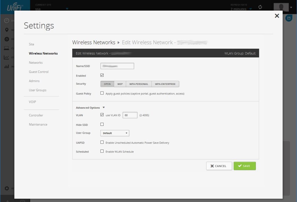
On the MikroTik, a VLAN is added to the Ethernet port, assigned ID 88, and discovery is disabled on the VLAN.
/interface vlan
add comment=SSID2-verejne interface=ether2 mtu=1520 name=vlan88-guest vlan-id=88
/ip neighbor discovery
set vlan88-guest comment=Verejne discover=no
As can be seen, only two MikroTik ports have been used.
Ether1 serves as the ADSL input, while Ether2 patches the public Wi-Fi onto a VLAN and carries the private Wi-Fi in UniFi.
The DHCP server and pools for the private network and the external public network are configured next.
/ip dhcp-server
add disabled=no interface=ether2 lease-time=20h10m name=Verejny
/ip pool
add name=soukromy-dhcp ranges=192.168.2.10-192.168.3.150
add name=verejny-dhcp ranges=192.168.1.101-192.168.1.150
/ip dhcp-server
add address-pool=verejny-dhcp disabled=no interface=vlan88-guest lease-time=\
20h10m name=Verejny
The address ranges must not be forgotten. Because more people will access the public Wi-Fi—around 100 a day—the author used a /23 allocation mask to provide more available addresses.
/ip address
add address=192.168.2.1/23 comment="Verejny adresy (500 adres)" interface=\
vlan88-guest network=192.168.2.0
add address=10.0.0.2/24 comment="PrivodniKonektivita z ADSL" interface=ether1 \
network=10.0.0.0
add address=192.168.1.1/24 comment="soukromy adresy" interface=ether2 network=\
192.168.1.0
The hotspot function is configured on the VLAN, and the firewall is set to determine when the hotspot is available to the public. The configuration merely involves clicking through the setup and is described in detail in the manual.
In this case, the hotspot should be available at specific times, during breaks. Access rules for the hotspot are therefore configured on the firewall.
/ip firewall filter
add chain=unused-hs-chain comment="Pristupova pravidla na hotspot" \
disabled=yes
# inactive time
add action=drop chain=forward comment="07:50 - 08:35" src-address=\
192.168.2.0/23 time=7h50m-8h35m,sun,mon,tue,wed,thu,fri,sat
# inactive time
add action=drop chain=forward comment=08:40-09:25 src-address=192.168.2.0/23 \
time=8h40m-9h25m,sun,mon,tue,wed,thu,fri,sat
# inactive time
add action=drop chain=forward comment="09:45 - 10:30" src-address=\
192.168.2.0/23 time=9h45m-10h30m,sun,mon,tue,wed,thu,fri,sat
# inactive time
add action=drop chain=forward comment="10:35 - 11:20" src-address=\
192.168.2.0/23 time=10h35m-11h20m,sun,mon,tue,wed,thu,fri,sat
add action=drop chain=forward comment="11:30 - 12:15" src-address=\
192.168.2.0/23 time=11h30m-12h15m,sun,mon,tue,wed,thu,fri,sat
# inactive time
add action=drop chain=forward comment=12:25-13:10 src-address=192.168.2.0/23 \
time=12h25m-13h10m,sun,mon,tue,wed,thu,fri,sat
# inactive time
add action=drop chain=forward comment=13.15-14:00 src-address=192.168.2.0/23 \
time=13h15m-14h,sun,mon,tue,wed,thu,fri,sat
While working on the firewall, the public hotspot is also secured with a few rules.
add chain=input dst-port=53 in-interface=vlan88-guest protocol=tcp
add chain=input dst-port=53 in-interface=vlan88-guest protocol=udp
add chain=input dst-port=67 in-interface=vlan88-guest protocol=udp
add chain=input dst-port=68 in-interface=vlan88-guest protocol=udp
add action=drop chain=input in-interface=vlan88-guest
add chain=forward in-interface=vlan88-guest
Most importantly, the rule separating the two subnets is configured to log any potential attack:
add action=drop chain=forward dst-address=192.168.0.0/16 in-interface=\
vlan88-guest log=yes log-prefix=VerejnyRozsahUtoci
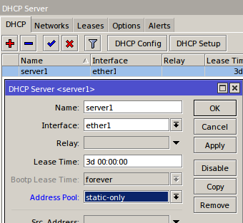
In the DHCP server section, using a static-only pool allows an address to be assigned only to a machine whose MAC and IP addresses are bound together in DHCP leases. This is a sensible precaution. Imagine someone plugging into an employee socket. Even if that person improperly enters the private address range, there is still no guarantee that they will obtain access to whatever they want.
Those who want to be true purists can configure queue rules to limit data flow for users on the public hotspot and assign them a lower priority so that they do not overload the connection or restrict users on the private subnet.
The author's complete exported RSC file for the MikroTik configuration can be downloaded here: PracovniMikrotik